VOX AD30VT Amplifier Repair !!
After 2 years my VOX started cutting out during play - for a while I was able to rotate the AMP selector knob and "kickstart" the thing back to life but eventually it died altogether! The power lamp illuminated when the amp was switched on but no other indicator lamps were lit and there was NO output. Since the amp was out of warranty I elected to open it up and see what I could do. If your VOX AD30VT has the same problem read on, there's hope !!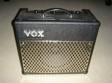
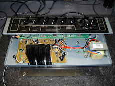
Remove the chassis...
Remove the back panel - then 4 screws on each side of the cabinet and the 3 remaining on the back that secure the amplifier chassis to the cabinet. Disconnect the speaker wires and remove the chassis, place it on you work table...
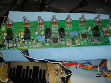
Remove the knobs...
remove all the knobs by lifting straight up - don't use any tools as you may damage the plastic, just use both hands and pinch the "chicken head" knobs on each end and pull. Then unscrew the retaining nuts on each control as well as the large nut on the input jack. Push the input jack out of the hole in the chassis.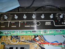
Remove the main board bottom screws...
Carefully unplug the 12AX7 tube from the power board. Tip the chassis on end and use an angled, phillips head screwdriver to remove the two nasty screws that secure the main board from the bottom.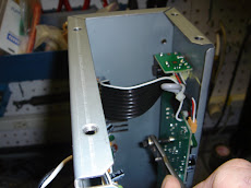
Found the problem !!
I pulled a schematic off the web - and began by checking the supply voltages. Voltages coming in to the main board from the power board were all good. Checking for the +3v and -3v to the various IC's on the board I found several were not there! Since IC4 is the primary processor I thought it would be a good idea to try and get the missing +3v to pin 94 somehow...
+3v Available...
Checking the schematic I noticed +3v available on pin 1 of CON6 - this is an unused connector position on the main board (likely used for additional features in a higher end model). A quick voltage check confirmed the voltage was there so I soldered a short piece of wire into the pin 1 hole to act as a terminal post.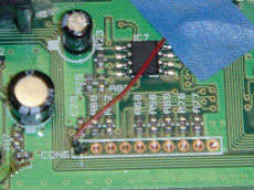
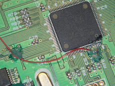
Solder pin 94
Pin 94 of IC5 needs the +3v but the pins on this IC are tiny - soldering directly to the pin would likely cause a solder bridge across a few pins that would be a mess. Pin 94's circuit board "land" is a short path to a small circuit board feed-through "sleeve" that is supposed to connect to another layer of the board where the +3v comes from. I carefully scraped the protective clear glaze off the tiny sleeve end that looks like a small hole at the end of the short "land" piece pin 94 is soldered to. Then I carefully soldered a #28 jumper wire to this point...Connect the jumper
I soldered the other end of this jumper to the piece of wire I secured to pin 1 of CON6. This effectively brought the missing +3v to pin 94 on IC5.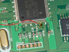
Tested OK ! then shock-proofed...
I couldn't wait - plugged the 12AX7 back in, connected the speaker with jumper cords, connected the power cord, hit the power switch and tah dah !! all the indicator lights cycled through their start-up routine and the "preset" and "tap" lamp stayed on. A quick guitar test showed everything working as expected. I secured the jumper wire in several spots and the pin 94 connection with silicon to keep the whole thing from shaking loose in the high vibration environment. Reversing all the dismantling steps above I buttoned the whole thing back up and am enjoying my VOX again!!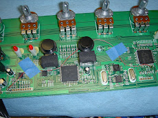
1 comment:
The pics are hard to zoom in on the see the actual connection at the Processor chip. I have a micro soldering iron that can hit those tiny legs. I just want to make sure I have the right place.
Post a Comment